The following schematics show the circuits used in our project.
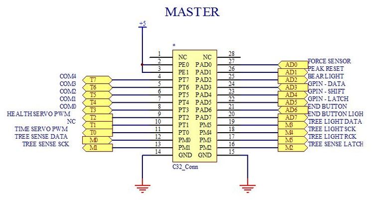
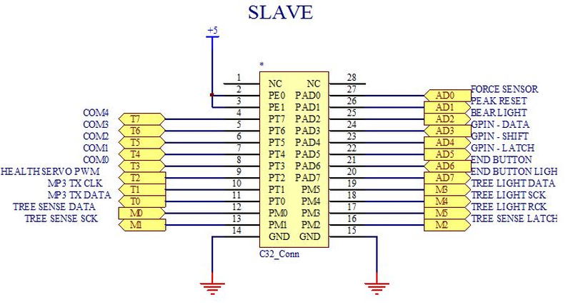
C32 CONNECTIONS
A master-slave set up was used for communication between our two C32s. GPIN 0 is for Card Read 0, GPIN 1 is for Card Read 1, GPIN 2 is for Card Read 2, GPIN 3 is for the hammer sensor, and GPIN 4 is for the end of game button sensor
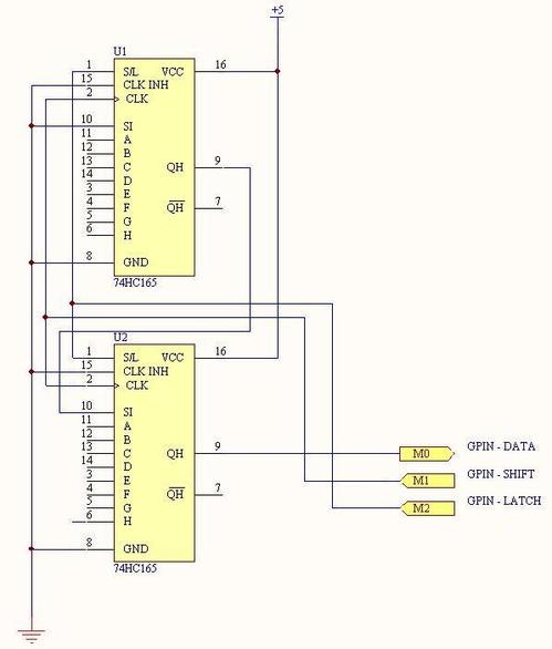
D/A SHIFT REGISTER (GPIN)
The hammer detection IR Schmitt Triggers were on a pin, the IR Schmitt triggers for the access card tape sensors were on other pins for each access card data location
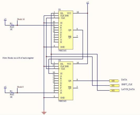
P/S SHIFT REGISTER (READING TREE HOOKS)
Hooks were on A-H of each register
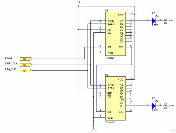
S/P SHIFT REGISTER (TREE LED LIGHTING)
The LEDs were on A-H of each register
FORCE SENSOR AND LIGHTS AROUND BEAR
A ring of white LEDs around Oski would light up when it was ready to be hit. Each of the 8 bear lights were in parallel through a single 2N7000

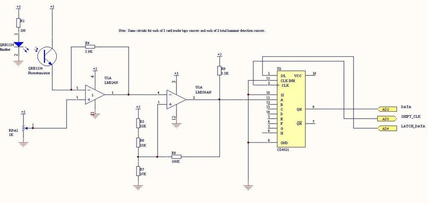
TAPE SENSOR
The same circuit was used for the two tape sensors in the access card reader and the two hammer detection sensors
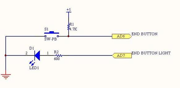
END OF GAME BUTTON
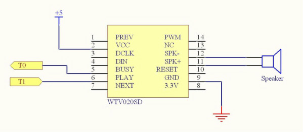
MP3 PLAYER
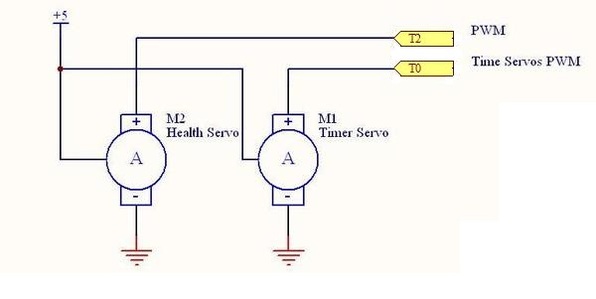
SERVO MOTOR
The part of the circuit labeled health servo served to show players the status of their bear as they hit it with the hammer. There was a health servo for each player, but only one timer servo.
*Note: we placed a variety of different sized bypass capacitors throughout all our circuits to reduce noise.
